|
|
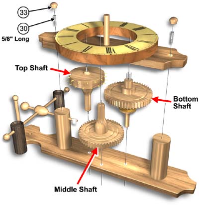
PAGE 3. FRONT PLATE
- Insert the (3) shaft assemblies into the back plate #1 nylon bearings.
- Align the top plate #2 over the shaft assembly ends.
(Make sure shaft assemblies rotate freely)
- Secure with (2) screws #30 (5/8" long)
(Do not use longer screws)
- Insert the (2) screw caps #33 into the front plate #1.
|
|

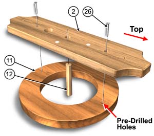
PAGE 3. DIAL
- Align the dial #11 to the pre-drilled holes on the back
of front plate #2 and attach with (2) screws #26.
- Carefully cut out paper dial. Apply thin coat of glue to
front side of front plate #2 Spread thin with finger.
Wait till glue is tacky. Press on paper dial.
- Press spindle #12 into front plate #2.
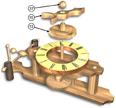
 PAGE 3. HOUR HAND and WEIGHTS
- Load front gear #13 onto spindle #12
(Carefully allign teeth with pins on bottom shaft)
- Press hour hand #15 onto tapered bush on front gear #13
(This is also how you set the time)
- Press knob #37 onto end of spindle #12
- Thread braided cord #48 around pulley #16.
- Slide heat shrink tube #56 onto each end of cord.
- Thread left end of cord through large metal weight #46
and right end of cord through small metal weight #47.
- Slide heat shrink tube #56 over each end of cord and
carefully hold next to candle flame or heat gun until it
shrinks onto cord. (DO NOT hold above flame).
|